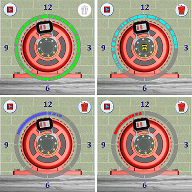
Data Quality Analyzer
Uses a 2D color-coded dot system to evaluate measurement quality and detect potential bearing wear, avoiding the distracting, screen-dominating, and unsafe 3D scan views that add no value to the alignment process.
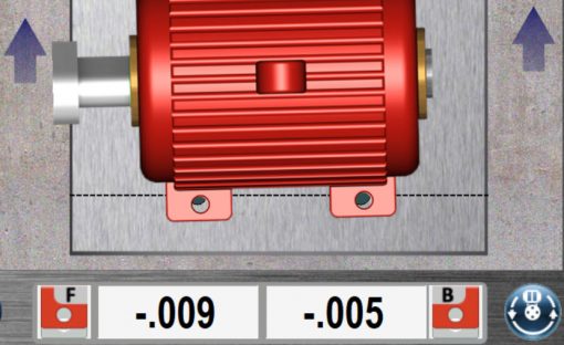
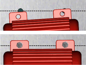
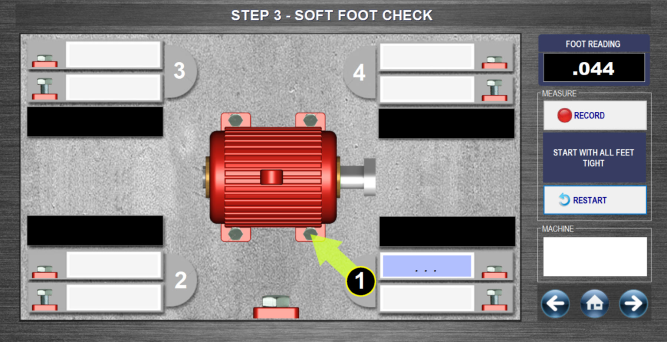
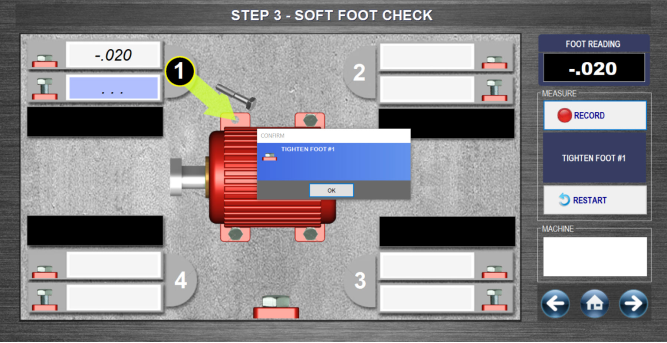
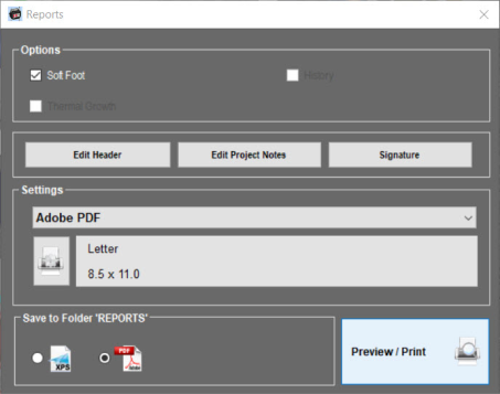
Soft Foot Analyzer
Provides an easy-to-use, color-coded display with recommended shim values, detects soft foot issues, allows retaking measurements on any foot in any order, and includes the results in the final Machine Report.
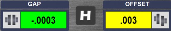
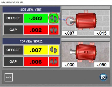
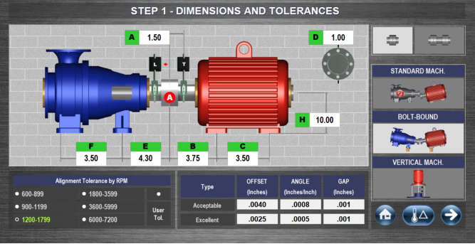
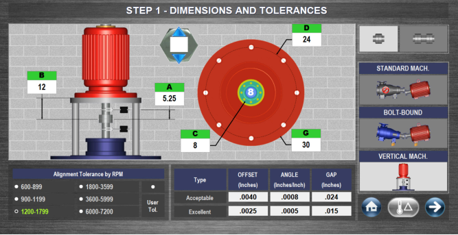
Recommended Tolerances
Compare measurement results against a built-in two-tier tolerance table (Excellent and Acceptable), displaying color-coded feedback, Green for Excellent, Yellow for Acceptable, and Red for Out of Tolerance, to clearly indicate alignment status.
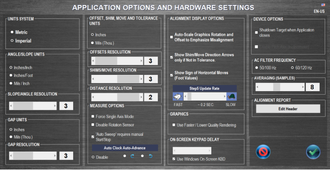
User-Defined Tolerances
Allows the end user to customize recommended tolerances to meet specific requirements set by the asset OEM or to apply alternative tolerances based on user preference.
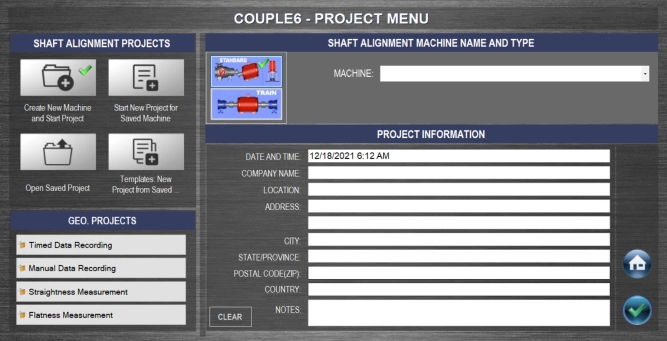
Save Machine Data & Files
All data, including plant location, machine names, tolerances, dimensions, and measurement results, is stored dynamically for easy reuse and template creation, streamlining future alignment tasks.
Machine Templates
Allows users to enter dimensions, tolerances, and coupling type for frequently used motor setups, with the ability to open previous alignment files to autofill all relevant data, streamlining the process to just mounting, selecting the file, performing soft foot, collecting data, and making corrections as needed.
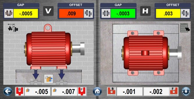
Flip It™
Provides the ability to flip the screen for correct machine orientation based on the user’s viewing position, with full functionality maintained even in Zoom mode on a Windows tablet.
Printed Reports
Couple6 alignment software generates full-color reports that can be saved as PDFs and emailed directly from a tablet or Windows PC with an active internet connection.
Digital Signature
Includes a signature block that allows technicians or supervisors to sign the report using a finger or the included stylus.
Image Capture
Provides the ability to capture photos of the application and store them within the data file for seamless inclusion in reports, enhancing documentation and clarity.
Vertical Machine
Calculates shim and move values for flange-mounted motors by easily measuring vertical machine alignment, simply enter the flange bolt quantity and diameter, coupling diameter, and flange outside diameter.
Vertical Machine Real-Time Move Screen
Provides realistic, real-time updated graphics and values that display live feedback during vertical machine corrections, allowing quick reference point changes, ideal for vertical machinery adjustable at the flange.
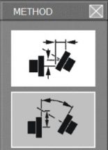
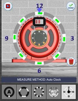
Auto Clock™ Data Taking
Primarily used for vertical applications where the accelerometer cannot be used, this method records data at up to 8 “clock” positions, requiring a minimum of 3 points (4-8 recommended), with data collected at intervals of at least 45 degrees.
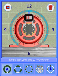
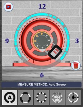
Auto Sweep™ Data Taking
Automatically captures readings by rotating between any two positions with Auto or Manual start and stop sweeps, generating data points as the shafts rotates, recording up to 1,000 points per data set with a minimum sweep of 40 degrees that crosses a polar coordinate.
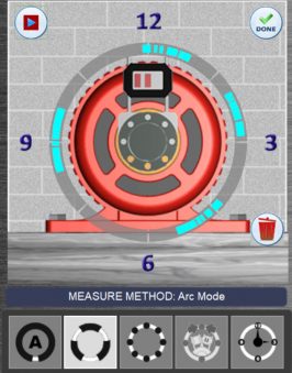
Arc Mode™ Data Taking
Allows starting and stopping at any point in the motor’s rotation multiple times, ideal for situations with obstructions blocking the laser or preventing full rotation where partial sweeps are combined as long as they total at least 40 degrees and cross a polar coordinate.
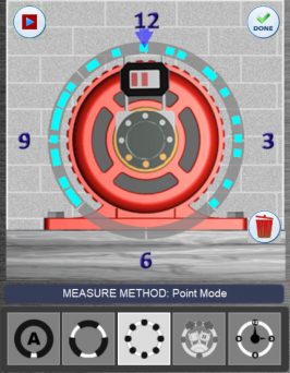
Point Mode™ Data Taking
For harsh environments with high vibration, it allows rotating to any clock position to take data points, requiring at least five points, using data averaging to reduce measurement noise and accurately calculate misalignment results.
Uncoupled Swipe™ Data Taking
For non-rotating shaft applications, this method involves rotating the laser to any position and slowly sweeping the target past the laser to capture data points, requiring a minimum of five points, including one within 10 degrees of a polar coordinate
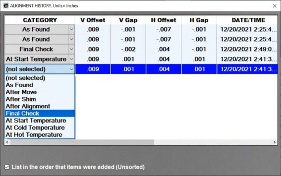
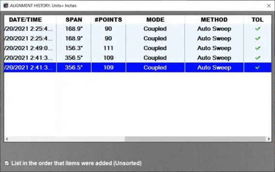
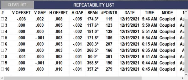
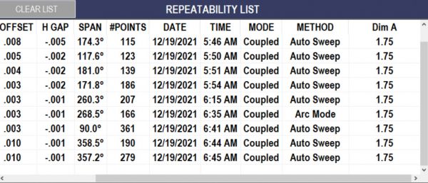
Repeatability Results Table with History
Stores up to 99 sets of detailed alignment results, allowing selection of individual readings or averaging multiple readings, making it ideal for unstable bases or “loose” machines, with the option to archive data points to the History table under selectable categories.
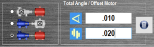
Thermal Growth – Coupling Offset
Allows entry of thermal growth offsets at the coupling so that when aligning “in tolerance,” the motor is intentionally positioned with these offsets applied, values usually provided by equipment OEMs, and is widely used in the maritime industry for accurate calculations.
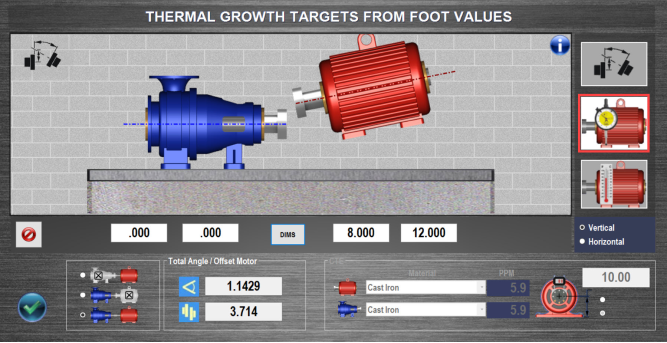
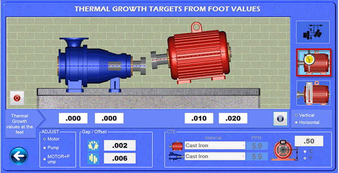
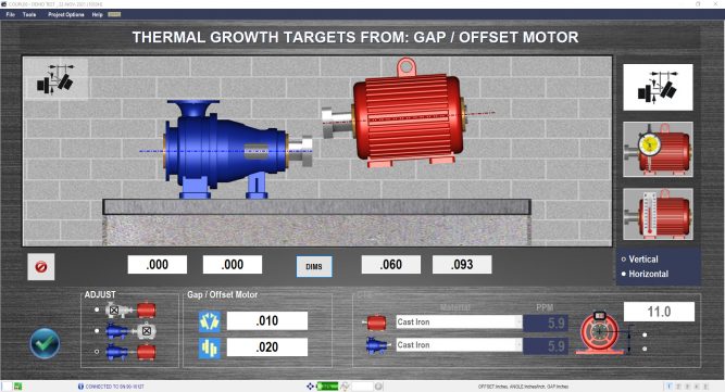
Thermal Growth – Foot Value Offset
Determines and applies thermal growth offsets at the feet by allowing entry of thermal growth at the coupling, expected foot value changes, or temperature changes, with machine materials selected from a built-in database, to automatically adjust misalignment values during alignment.
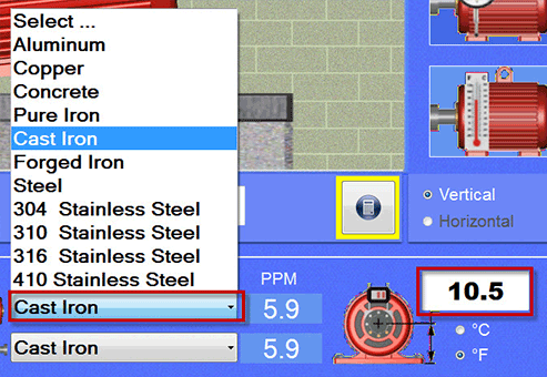
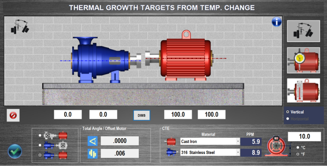
Thermal Growth – Temperature
Temperature calculations provide precise adjustments to alignment values by accounting for temperature-induced expansions or contractions of machine components, ensuring accurate and reliable machine positioning throughout varying operating conditions.
Bolt Bound/Base Bound w/Move Screen
This feature lets you move the stationary machine when the movable one can’t be adjusted, locking feet on both machines to recalculate shim and move values for bolt- or base-bound conditions, with graphical support and Duo-Plane™ functionality.
Spacer Shaft – 7 Data Formats
Select from seven realistic data formats for spacer shafts by choosing the coupling type and entering the spacer shaft length in Step 1, after which the results and Step 5 move data are formatted accordingly, defaulting to Gap A/Gap B, while shim and move values remain unchanged.
Machine Train 3
Optimize moves for three (3) coupled machines by letting you build a custom train, input thermal growth targets, collect data, and minimize shims and movements, with options to select a reference machine, track data, and generate a full report.
Machine Train 10
Optimize moves for 3-10 coupled machines by letting you build a custom train, input thermal growth targets, collect data, and minimize shims and movements, with options to select a reference machine, track data, and generate a full report.
Manual/Timed Data Recorder/Analyzer
The Geometric app offers two data-taking modes, Timer Mode for recording machinery movement at custom time intervals and Manual Mode for manual recording of thermal growth or general data, with results displayed in colorful scaled plots and up to 32,000 data points.
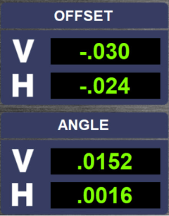
Straightness Data Recorder/Analyzer
The Geometric app records straightness measurements using A-987 T/L Bases, calculates TIR results with a Best Fit algorithm, presents summaries and graphs of V offset and angle or V&H offset and angle depending on system, plots all axes in the graph and results table, and can store up to 32,000 data points.
Flatness Data Recorder/Analyze
The Geometric app records flatness measurements with the A-987 T/L Bases, calculates TIR results using the Best Fit algorithm, presents summaries and graphs of V offset and angle, plots all axes in the graph and results table, and stores up to 32,000 data points.
 Stop by our booth #728 at SMRP’s 33rd Annual Conference October 6–9

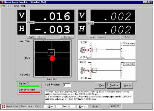
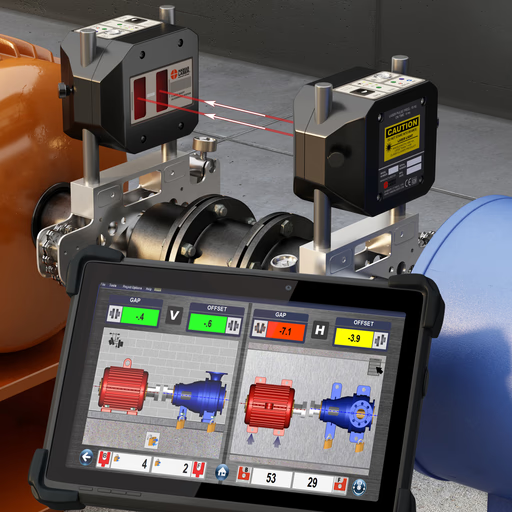


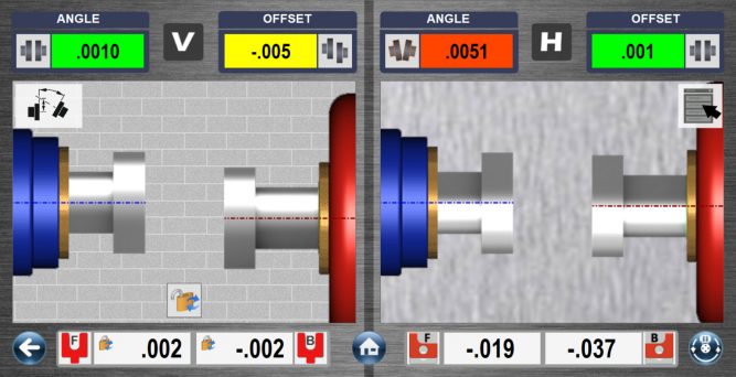


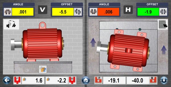


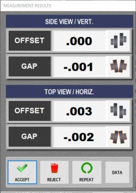


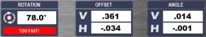
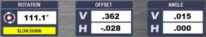
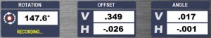
 Here are the 4 axes (T-1290) live alignment data. It is always a good idea to keep an eye on the raw data while recording to make sure no bad data points get into the data set. This can also be used to do a “poor man’s” uncoupled alignment using Point Mode or Auto Clock™
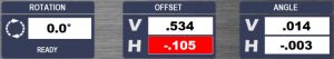


