

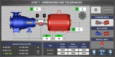
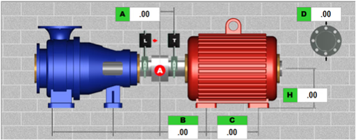
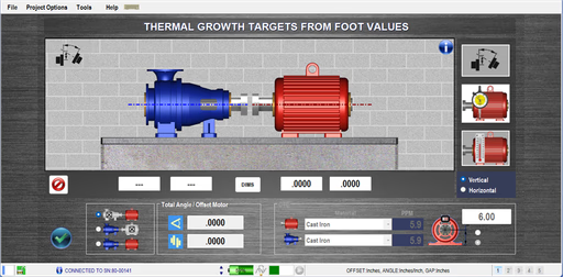
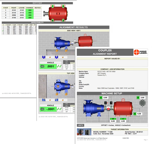
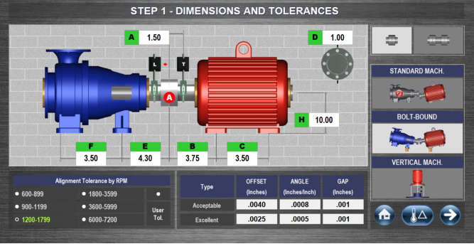
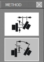
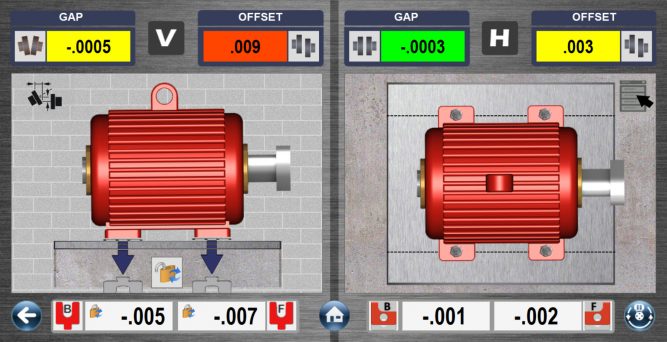
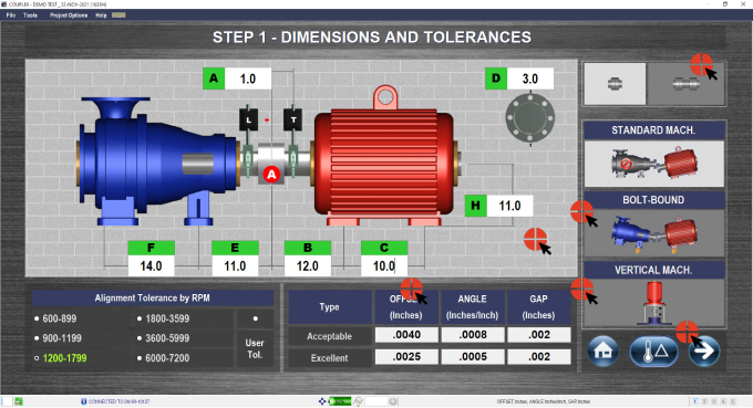
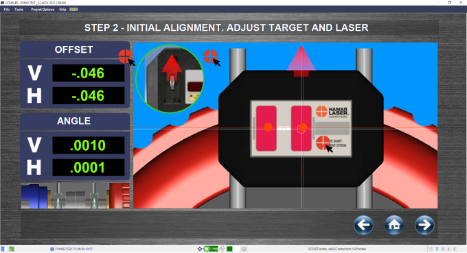
Aligns two rotating machines connected by a single coupling. Includes measuring and correcting angular and offset misalignments between machine shafts to achieve optimal alignment.
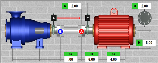
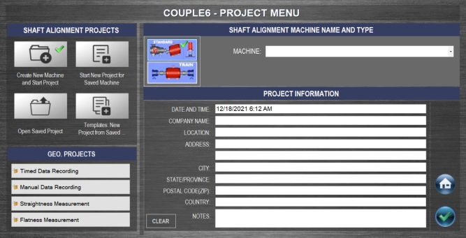
Aligns the shafts of two rotating machines that are connected by a spacer or jack shaft to ensure their rotational centerlines collinear. There are 7 different formats that can be used in this type of alignment.
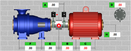
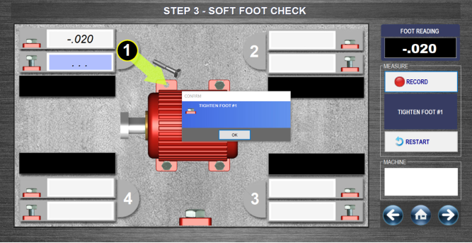
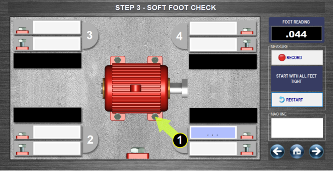
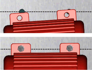
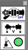
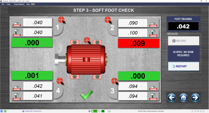
Locks, unlocks different combinations of the moveable and stationary machine feet to see how it affects the alignment solution. The graphics and shim values automatically update.
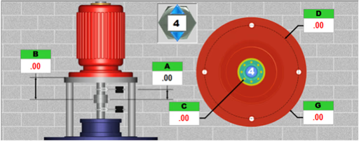
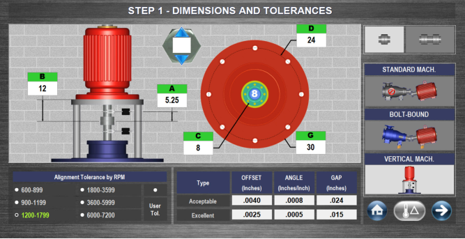
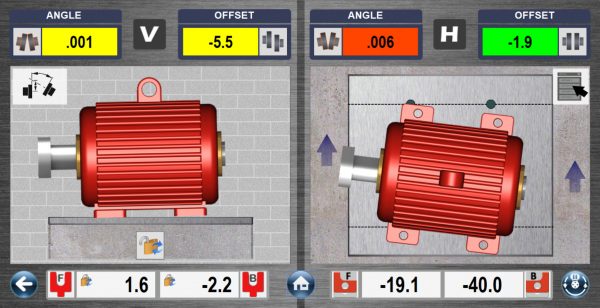
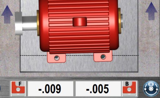
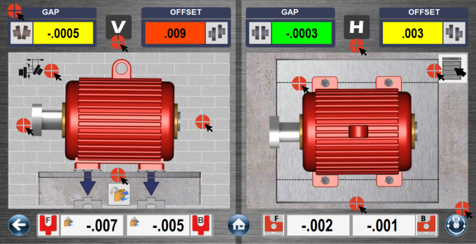
is the industry’s only vertical alignment display with live graphical displays of the motor’s alignment along with shim values for all bolt-hole locations. This alignment is for flange-mounted vertical motors.
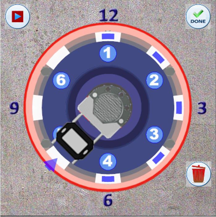
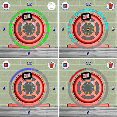
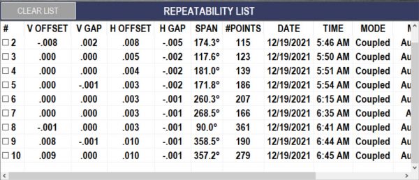
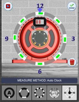
Auto Clock™ has 8 clock positions to choose from instead of 3 or 4, simply rotate the laser/target to that position, and click record. A minimum of three points in a 90-degree arc is required to calculate results.
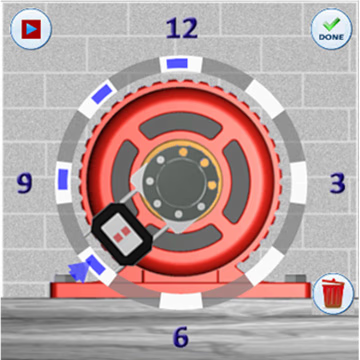
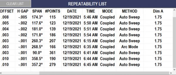
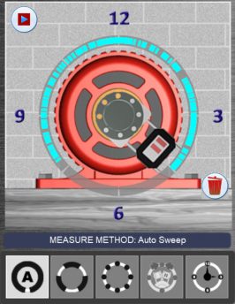
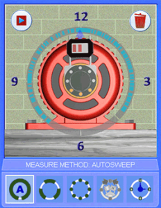
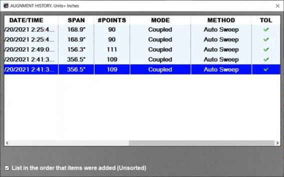
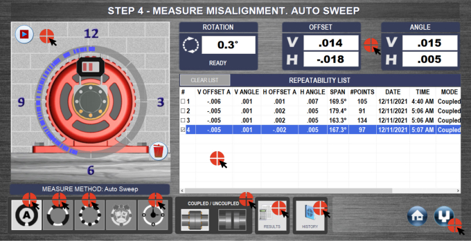
Auto Sweep™ starts at any clock position in the sweep and sweeps to any other point with a minimum of 60 degrees. This mode auto-calculates when the sweep is stopped.
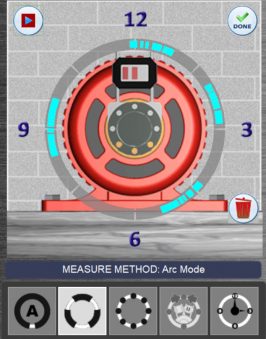
Arc Mode™ starts and stops at any point in the motor’s rotation circle multiple times. Use this mode if there are obstructions that block the laser beam or prevent a full rotation.
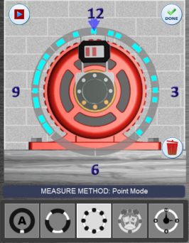
Point Mode™ rotates the laser/target to any clock position in the rotation and click Record to take a data point at that location. A minimum of five points is needed and used to perform uncoupled alignments.
Uncoupled Swipe™ makes taking data much easier. Rotate the laser to any clock position, sweep the target by it, where it automatically records the data point. (Only Available on X-880 and X-990 PRO)
Vertical Auto Clock™ has 8 clock positions to record data, just rotate the laser/target to that position, and click record. The Rotation Sensor is disabled in this to allow for physical movement and data taking at each position.
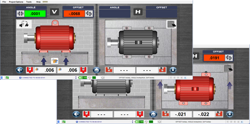
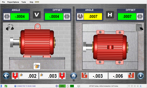


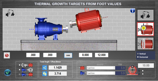


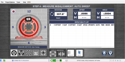
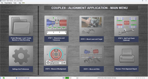
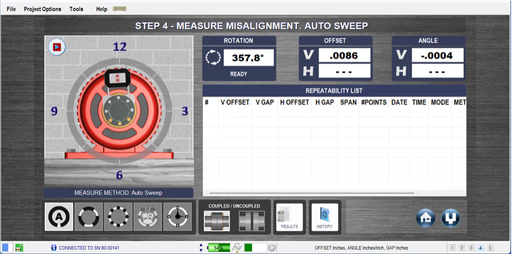
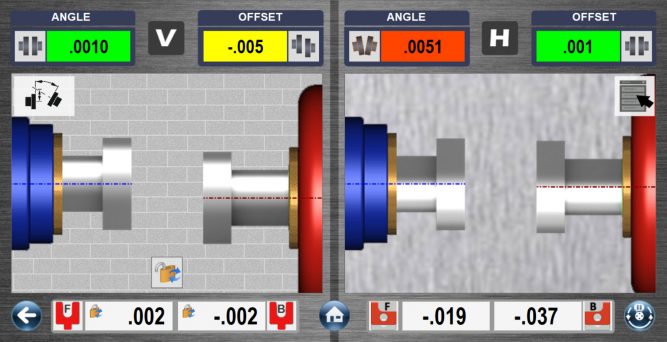
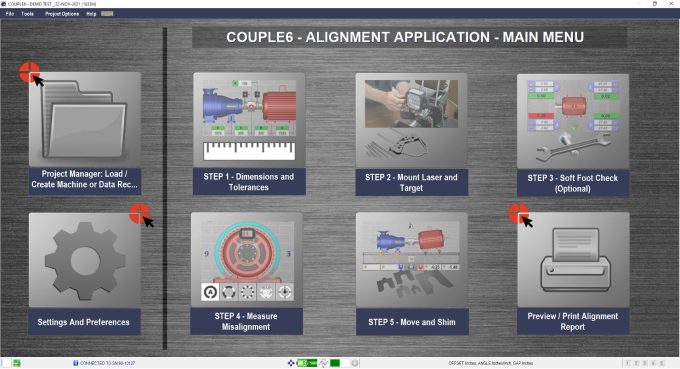
Couple6 provides 3-5 axes of live alignment data in our Step 4 -Measure Misalignment screen.
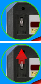
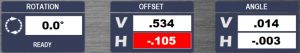
This is the Rotation Axis (3rd or 5th axis) Live Display and Status Bar. It shows the continuously updating rotational position of the target. Zero degrees means the target is located at 12:00, 90 degrees means 3:00. The data taking status is also shown here.
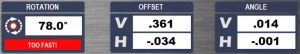
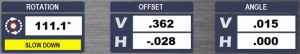

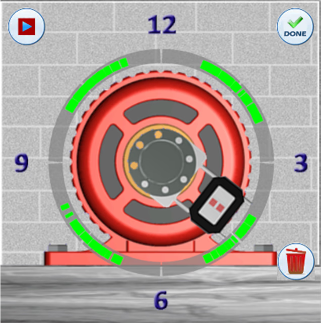
Here the user is recording data at the proper speed in Auto Sweep™ or Arc Mode™
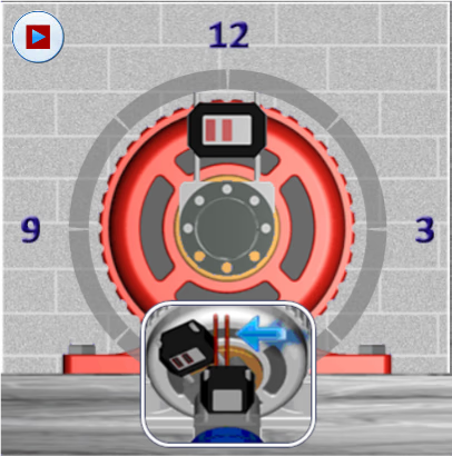
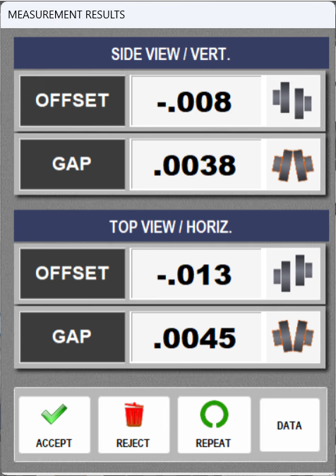
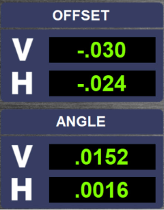
 Here are the 4 axes (T-1290) live alignment data. It is always a good idea to keep an eye on the raw data while recording to make sure no bad data points get into the data set. This can also be used to do a “poor man’s” uncoupled alignment using Point Mode or Auto Clock™


